This document describes tools for calibrating a Z endstop and for performing adjustments to bed leveling screws.
Calibrating a Z endstop
An accurate Z endstop position is critical to obtaining high quality prints.
Note, though, the accuracy of the Z endstop switch itself can be a limiting factor. If one is using Trinamic stepper motor drivers then consider enabling endstop phase detection to improve the accuracy of the switch.
To perform a Z endstop calibration, home the printer, move the head to a position near the center of the bed, navigate to the OctoPrint terminal tab, and run:
Z_ENDSTOP_CALIBRATE
Then follow the steps described at
“the paper test” to determine the
actual distance between the nozzle and bed at the given location. Once
those steps are complete one can ACCEPT the position and save the
results to the config file with:
SAVE_CONFIG
It’s preferable to use a Z endstop switch on the opposite end of the Z
axis from the bed. (Homing away from the bed is more robust as then it
is generally always safely to home the Z.) However, if one must home
towards the bed it is recommended to adjust the endstop so that it
triggers a small distance (eg, .5mm) above the bed. Almost all endstop
switches can safely be depressed a small distance beyond their trigger
point. When this is done, one should find that the
Z_ENDSTOP_CALIBRATE command reports a small positive value (eg,
.5mm) for the Z position_endstop. Triggering the endstop while it is
still some distance from the bed reduces the risk of inadvertent bed
crashes.
Some printers have the ability to manually adjust the location of the physical endstop switch. However, it’s recommended to perform Z endstop positioning in software with Klipper - once the physical location of the endstop is in a convenient location, one can make any further adjustments by running Z_ENDSTOP_CALIBRATE or by manually updating the Z position_endstop in the configuration file.
Adjusting bed leveling screws
The secret to getting good bed leveling with bed leveling screws is to utilize the printer’s high precision motion system during the bed leveling process itself. This is done by commanding the nozzle to a position nearest each bed screw and then adjusting that screw until the bed is a set distance from the nozzle. Klipper has a tool to assist with this. In order to use the tool it is necessary to specify each screw XY location.
This is done by creating a [bed_screws] config section. For example,
it might look something similar to:
[bed_screws]
screw1: 100,50
screw2: 100,150
screw3: 150,100
If a bed screw is under the bed, then specify the XY position directly above the screw. If the screw is outside the bed then specify an XY position closest to the screw that is still within the range of the bed.
Once the config file is ready, run RESTART to load that config, and
then one can start the tool by running:
BED_SCREWS_ADJUST
This tool will move the printer’s nozzle to each screw XY location and then move the nozzle to a Z=0 height. At this point one can use the “paper test” to adjust the bed screw directly under the nozzle. See the information described in “the paper test”, but adjust the bed screw instead of commanding the nozzle to different heights. Adjust the bed screw until there is a small amount of friction when pushing the paper back and forth.
Once the screw is adjusted so that a small amount of friction is felt,
run either the ACCEPT or ADJUSTED command. Use the ADJUSTED
command if the bed screw needed an adjustment (typically anything more
than about 1/8th of a turn of the screw). Use the ACCEPT command if
no significant adjustment is necessary. Both commands will cause the
tool to proceed to the next screw. (When an ADJUSTED command is
used, the tool will schedule an additional cycle of bed screw
adjustments; the tool completes successfully when all bed screws are
verified to not require any significant adjustments.) One can use the
ABORT command to exit the tool early.
This system works best when the printer has a flat printing surface (such as glass) and has straight rails. Upon successful completion of the bed leveling tool the bed should be ready for printing.
Fine grained bed screw adjustments
If the printer uses three bed screws and all three screws are under the bed, then it may be possible to perform a second “high precision” bed leveling step. This is done by commanding the nozzle to locations where the bed moves a larger distance with each bed screw adjustment.
For example, consider a bed with screws at locations A, B, and C:
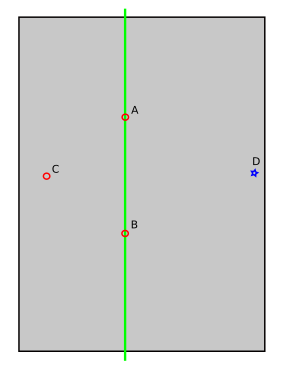
For each adjustment made to the bed screw at location C, the bed will swing along a pendulum defined by the remaining two bed screws (shown here as a green line). In this situation, each adjustment to the bed screw at C will move the bed at position D a further amount than directly at C. It is thus possible to make an improved C screw adjustment when the nozzle is at position D.
To enable this feature, one would determine the additional nozzle coordinates and add them to the config file. For example, it might look like:
[bed_screws]
screw1: 100,50
screw1_fine_adjust: 0,0
screw2: 100,150
screw2_fine_adjust: 300,300
screw3: 150,100
screw3_fine_adjust: 0,100
When this feature is enabled, the BED_SCREWS_ADJUST tool will first
prompt for coarse adjustments directly above each screw position, and
once those are accepted, it will prompt for fine adjustments at the
additional locations. Continue to use ACCEPT and ADJUSTED at each
position.
Adjusting bed leveling screws using the bed probe
This is another way to calibrate the bed level using the bed probe. To use it you must have a Z probe (BL Touch, Inductive sensor, etc).
To enable this feature, one would determine the additional nozzle coordinates near the screws and add them to the config file. For example, it might look like:
[screws_tilt_adjust]
screw1: -5,30
screw1_name: front left screw
screw2: 155,30
screw2_name: front right screw
screw3: 155,190
screw3_name: rear right screw
screw4: -5,190
screw4_name: rear left screw
horizontal_move_z: 10.
speed: 50.
samples: 3
sample_retract_dist: 2.
samples_result: median
screw_thread: CW-M3
One can indicate the number of times to repeat probe on each screw and if the value is the median or the average read probe.
The screw1 is always the reference point for the others, so the system
assumes that screw1 is in the correct height.
Then to use this feature you must preform every time G28 before
SCREWS_TILT_CALCULATE and after bed is probed you get an output like this:
Send: G28
Recv: ok
Send: SCREWS_TILT_CALCULATE
Recv: // front left screw (Base): X -5.0, Y 30.0, Z 2.48750
Recv: // front right screw : X 155.0, Y 30.0, Z 2.36000 : Adjust -> CW 01:15
Recv: // rear right screw : X 155.0, Y 190.0, Z 2.71500 : Adjust -> CCW 00:50
Recv: // read left screw : X -5.0, Y 190.0, Z 2.47250 : Adjust -> CW 00:02
Recv: ok
This means that:
- front left screw is the reference point you must not change it.
- front right screw must be turned clockwise 1 full turn and a quarter turn
- rear right screw must be turned counter-clockwise 50 minutes
- read left screw must be turned clockwise 2 minutes (not need it's ok)
Repeat the process several times until you get a good level bed, normally when all adjusts are below 6 minutes.