This document describes how the STM32F0 port operates and how to work with tiny CAN-enabled boards.
Required components
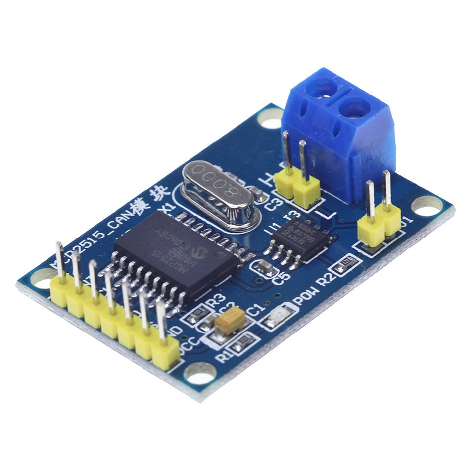
MCP2515 module
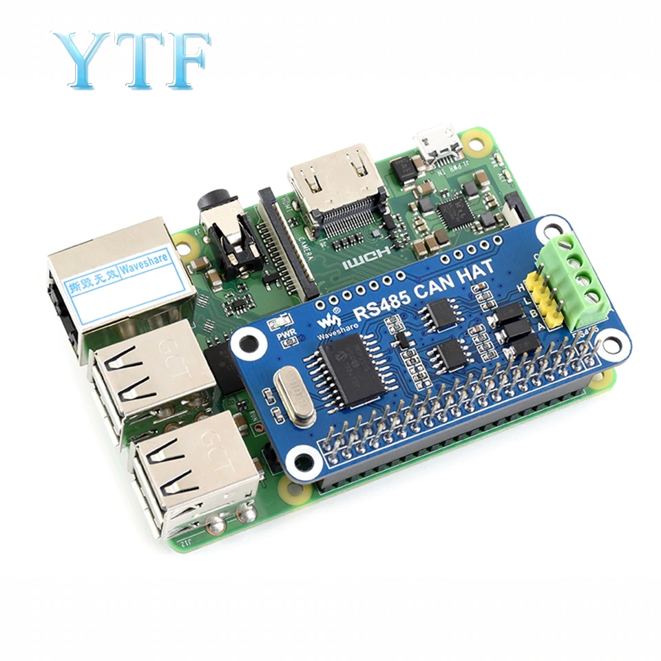
 or this
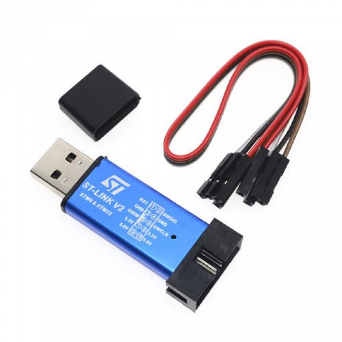
St-link dongle
Adding CAN bus to Raspberry Pi
(Based on Quick Guide https://www.raspberrypi.org/forums/viewtopic.php?f=44&t=141052)
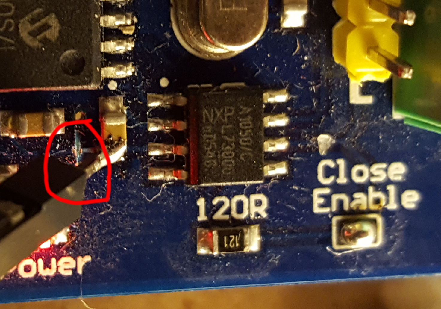
First of all, (only if you have small CAN module) it’s necessary to modify the CAN-module from ebay, because it has only one VCC pin, but the MCP2515 needs to be powered from 3V3 and the TJA1050 CAN-transceiver needs to be powered from 5V. Powering both chips from 5V would work, but then a level-shifter for the SPI would be needed. The Pi’s GPIO pins are NOT 5V tolerant. Cut a trace on the PCB and soldered a pin onto the trace to deliver 5V only to the TJA1050. Be sure to cut the trace before the capacitor:
Next connect the module:
| MCP2515 | Raspberry Pi |
|---|---|
| VCC | 1 (3V3) |
| TJA 1050 VCC | 2 (5V) |
| GND | 6 (GND) |
| CS | 24 (CE0) |
| MISO | 21 (MISO) |
| MOSI | 19 (MOSI) |
| SCK | 23 (SCK) |
| INT | 22 (GPIO25) |
Install can-utils:
sudo apt-get install can-utils
To activate the driver for the MCP2515 you have to add a kernel overlay, to do so edit the /boot/config.txt
sudo nano /boot/config.txt
And add the following lines (set oscillator value according to crystal on your board):
dtparam=spi=on
dtoverlay=mcp2515-can0,oscillator=8000000,interrupt=25
dtoverlay=spi1-1cs
Now reboot, after the reboot try to setup the the can interface:
sudo ip link set can0 up type can bitrate 500000
If no errors occurred, the can interface should be ready now. To make the CAN-interface permanent, add the following lines to /etc/network/interfaces
auto can0
iface can0 can static
    bitrate 500000
Communicating over CAN
Use “Serial over CAN” emulator software to establish connection: https://github.com/Delsian/CanSerial
Install st-link on Raspberry Pi
sudo apt-get update
sudo apt-get install cmake
sudo apt-get install libusb-1.0-0-dev
git clone https://github.com/texane/stlink stlink-repo
cd stlink-repo
make
cd build/Release/
sudo make install
Copy to /etc/udev/rules.d/49-stlinkv2.rules:
# stm32 discovery boards, with onboard st/linkv2
# ie, STM32L, STM32F4.
# STM32VL has st/linkv1, which is quite different

SUBSYSTEMS=="usb", ATTRS{idVendor}=="0483", ATTRS{idProduct}=="3748", \
    MODE:="0666", \
    SYMLINK+="stlinkv2_%n"

SUBSYSTEMS=="usb", ATTRS{idVendor}=="0483", ATTRS{idProduct}=="374b", \
    KERNEL!="sd*", KERNEL!="sg*", KERNEL!="tty*", SUBSYSTEM!="bsg", \
    MODE:="0666", \
    SYMLINK+="stlinkv2_%n"

SUBSYSTEMS=="usb", ATTRS{idVendor}=="0483", ATTRS{idProduct}=="374b", \
    KERNEL=="sd*", MODE:="0666", \
    SYMLINK+="stlinkv2_disk"

SUBSYSTEMS=="usb", ATTRS{idVendor}=="0483", ATTRS{idProduct}=="374b", \
    KERNEL=="sg*", MODE:="0666", \
    SYMLINK+="stlinkv2_raw_scsi"

SUBSYSTEMS=="usb", ATTRS{idVendor}=="0483", ATTRS{idProduct}=="374b", \
    SUBSYSTEM=="bsg", MODE:="0666", \
    SYMLINK+="stlinkv2_block_scsi"

SUBSYSTEMS=="usb", ATTRS{idVendor}=="0483", ATTRS{idProduct}=="374b", \
    KERNEL=="tty*", MODE:="0666", \
    SYMLINK+="stlinkv2_console"

# If you share your linux system with other users, or just don't like the
# idea of write permission for everybody, you can replace MODE:="0666" with
# OWNER:="yourusername" to create the device owned by you, or with
# GROUP:="somegroupname" and control access using standard unix groups.
Now “make flash” command can upload HEX into connected board
Pins allocation
Configurations with CAN and Serial port uses different pins, and during enumeration process firmware reports all possible pin names. But actually you can use only existing pins, not involved in communication. Wrong pins will generate shutdown.